


Amjad Traders
DIY Electronic Kit FM Stereo Radio Module 76-108MHz Wireless Transmitter Receiver Circuit PCB Board Soldering Practice Project
DIY Electronic Kit FM Stereo Radio Module 76-108MHz Wireless Transmitter Receiver Circuit PCB Board Soldering Practice Project
Couldn't load pickup availability
SPECIFICATIONS
Application: Electric Toy
Brand Name: IS
Condition: New
Feature 1: FM Radio Receiver DIY Kit
Feature 2: DIY FM Transmitter Kit
Feature 3: FM Receiver DIY Kit
High-concerned chemical: None
Operating Temperature: -25~85 Celsius
Origin: Mainland China
Package: SOP
Supply Voltage: DC 3V
Type: Logic ICs
is_customized: Yes

FM Radio Receiver Kit
http://attach01.oss-us-west-1.aliyuncs.com/IC/DIY-Manual/GY18041.pdf
1.Introduction:
The YFM-2 type radio circuit is very simple. The total number of components does not exceed 19. Although the number of components is not large, it includes two types of components: SMD and DIP which are suitable for novices and friends who want to practice soldering of SMD components.
2.Feature:
1>.Built-in digital automatic gain control (AGC) circuit
2>.Support the global frequency band 76-108Mhz
3>.DIY manual welding
4>.Simple and easy to operate
5>.Support radio memory function
3.Parameter:
1>.Item name: FM Stereo Radio Module DIY Kit
2>.Item Mode:YFM-2
3>.Work Voltage:DC 3V
4>.Work Current:19mA
5>.Work Frequency:76-108Mhz
6>.Output impedance:32ohm
7>.Work Temperature:-40℃~85℃
8>.Work Humidity:0%~95%RH
9>.Size(Installed):57*32*20mm


4.Application:
1>.Training welding skills
2>.Student school
3>.DIY production
4>.Project Design
5>.Electronic competition
6>.Graduation design
7>.Crafts collection
8>.Home decoration
9>.Souvenir collection
5.Installation Steps(Please be patient install!!!):
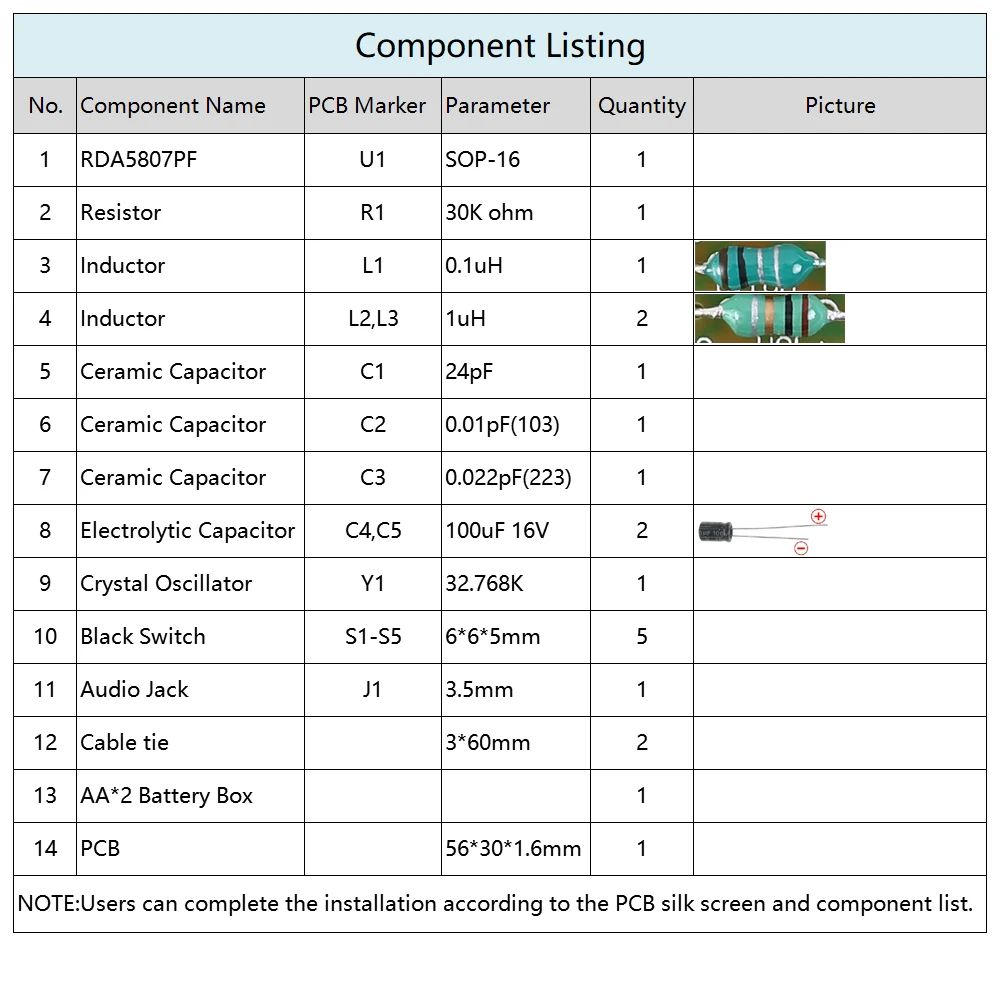
1>.Step 1: Install 1pcs SOP-16 RDA5807PF at U1.There is a dot on one corner of the IC and there is a rectangle pad on PCB where the Pin1 of IC can place on.These two marks are corresponding to each other and are used to specify the installation direction of the IC.
2>.Step 2: Install 1pcs 30K ohm Resistor at R1.
3>.Step 3: Install 1pcs 0.1uH Inductor at L1.
4>.Step 4: Install 2pcs 1uH Inductor at L2,L3.
5>.Step 5: Install 1pcs 32.768KHz Crystal Oscillator at Y1.
6>.Step 6: Install 1pcs 24pF Ceramic Capacitor at C1.
7>.Step 7: Install 1pcs 0.01pF(103) Ceramic Capacitor at C2.
8>.Step 8: Install 1pcs 0.022pF(223) Ceramic Capacitor at C3.
9>.Step 9: Install 5pcs 6*6*5mm Switch at S1-S5.
10>.Step 10: Install 1pcs 100uF 16V Electrolytic Capacitor at C4,C5. Please pay attention to the positive and negative poles. The shorter pin is the negative pole.
11>.Step 11: Install 1pcs 3.5mm Audio Jack at J1.
12>.Step 12: Connect battery box.Pay attention to positive and negative.
13>.Step 13: Use a cable tie to fasten the battery box.
14>.Step 8: Connect to power supply and enjoy the effect.


FM Transmitter Kit
Instruction Download link: http://attach01.oss-us-west-1.aliyuncs.com/IC/DIY-Manual/12232.pdf
1.Introduction:
1.Model: RF-02FM
2.Operating Current: 5-15mA
3.Operating Voltage: DC 3-6V
4.Transmission Distance: 5-50m\
5.Transmission Frequency: 88-108MHz
6.Audio Input: -15dB (max)
7.PCB Size: 53*40mm


